What is the digital I/O connector intended for, and how does it work?
On A320 and A325 (A320G), there are two inputs and two outputs. The two cameras differ in the way these pins can be used.
A320 / A310:
- The state (high or low voltage) on an input pin is used to start an event in the camera, for instance set a flag in the image stream or trig an alarm activity.
- The state (high or low voltage) on an output pin is controlled by an activity in the camera, for instance by the result of an alarm detection
A315, A325 (A320G) & A615, A655sc:
- The state (high or low voltage) on an input pin is used to mark images for use by an application.
- The state (high or low voltage) on an output pin is controlled by an application.
I/O data:
|
Pin |
Function |
Data |
|
1 |
IN 1 |
opto-isolated, 0 - 1.5V = low, 3 - 25 V = high |
|
2 |
IN 2 |
opto-isolated, 0 - 1.5V = low, 3 - 25 V = high |
|
3 |
OUT 1 |
opto-isolated, ON = supply (max. 100 mA), OFF = open |
|
4 |
OUT 2 |
opto-isolated, ON = supply (max. 100 mA), OFF = open |
|
5 |
Supply VCC |
6 - 24 VDC, max 200 mA |
|
6 |
Supply Gnd |
Gnd |
|
NOTE: Cable for digital I/O ports should be max 100m/328 ft. |
||
Related Articles
-
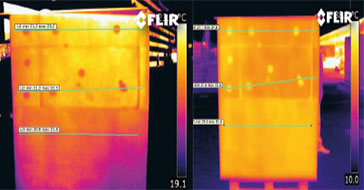 Application Story
FLIR cameras support analysis and diagnosis of external thermal insulation systems
Read the Story -
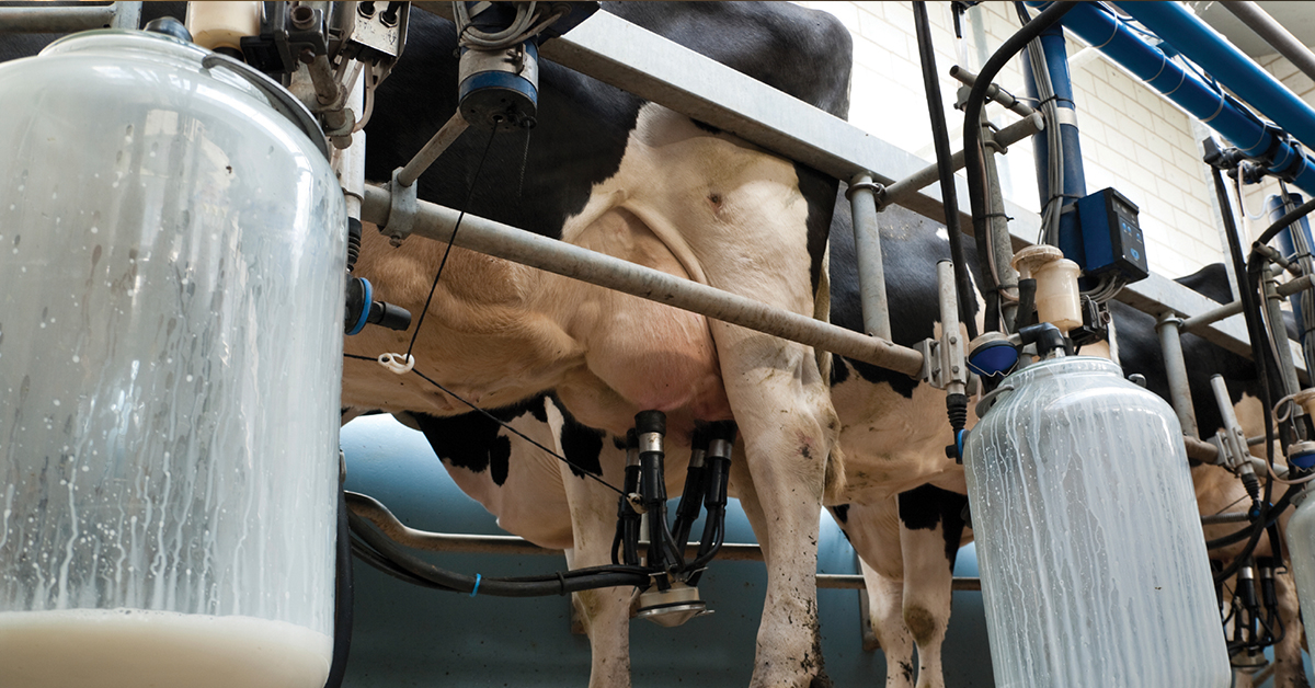 Case Study
Automatic Health Check in Dairy Farms Using FLIR Thermal Imaging Cameras
Read the Story -
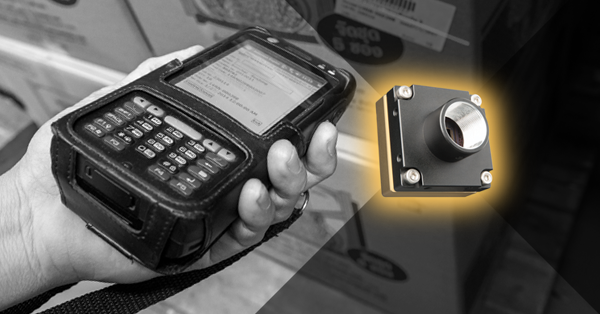 Deep Learning
Comparing Deep Learning Cameras with Smart Cameras
Read the Story